Sensor Configuration
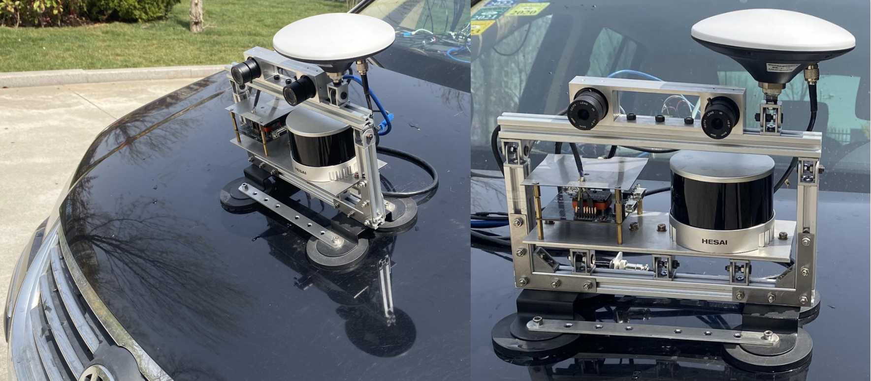
Different from traffic perception where sensors are generally installed on the car roof , we care more about the road surface area. To enlarge the image resolution and point cloud density of the road area, the sensors are placed on the bonnet with a certain pitch angle. The sensors are integrated with the aluminium profile framework and tightly fixed to ensure a rigid connection. The framework is mounted on the bonnet with four magnetic holders.
The IMU is installed just near the LiDAR on the same plate, so the calibration is simplified. Because the geomagnetic field is very weak and easily to be polluted, the heading (yaw) measurement is acquired from the dual-antenna RTK but not the IMU. The stereo cameras are placed above the LiDAR.The pitch angles are adjusted ensuring that they have as much common perspective as possible. The static preview distance of the camera is about 10m. The GNSS antenna is placed near the LiDAR so the measured information can directly represent the LiDAR motion.
The acquisition system runs at 5Hz so the LiDAR can acquire more points in one frame. The sensors are controlled and collected by the Jetson Xavier platform. To reduce the CPU burden, we directly collect data with multi-process in Python rather than ROS.
Cameras
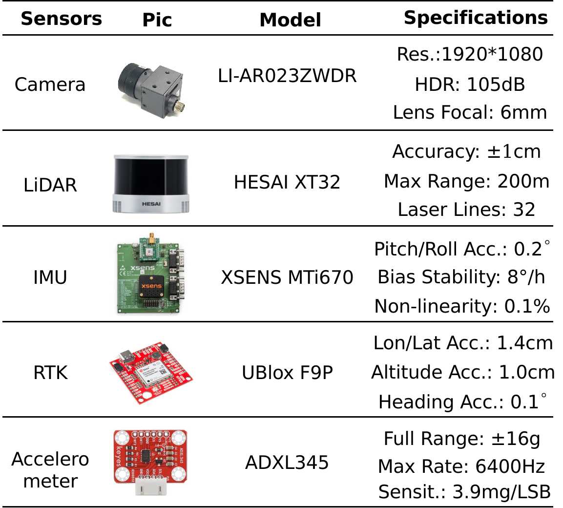
We adopt USB camera LI-AR023ZWDR from Leopard Imaging. It has 1/2.7' CMOS and 1920*1080 resolution (2M). It generates images with up to 105dB, which guarantees imaging quality in severe brightness change. Also, it has motion compensation to prevent ghost blur in multi-exposure HDR. This is very important because the camera captures the road surface, which has a bigger 'relative speed' because of the perspective effect. The two cameras are fixed with a designed rigid holder. The baseline is about 12 cm, resulting in a disparity range at about 20~140.
LiDAR
Road surface reconstruction is more sensitive to the LiDAR accuracy comparing with traffic objects perception. We finally adopt the XT32 from Hesai. It’s a mechanical rotating LiDAR with 32 scan lines. It is cost-effective and provides scans at typical ±1cm accuracy, which is higher than most existing products. We set the viewing angle as 100 degrees (i.e. [130, 230] degree) to cover only the forward road area.
GNSS-RTK
The RTK acquires the motion information of the LiDAR, which is utilized in the motion compensation and multi-frame fusion algorithm.
Specifically, it collects heading, longitude, latitude, altitude, and velocity signals. The horizontal accuracy is 1.4cm, and the altitude accuracy is 1cm.
The actual accuracy usually decreases because of the GNSS multi-path effect. So, in the post-processing pipeline, we only preserve the segments when the RTK reaches the highest accuracy.
IMU
In our data processing pipeline, the IMU provides the pitch and roll angles of the LiDAR. It runs at 400Hz.
Un-sprung Mass Accelerometer
We installed an ADXL345 tri-axes accelerometer on the swing arm of the front-right suspension. It measures the un-sprung mass acceleration when driving. The measurement range is 8g, and the rate is set to 800Hz. It raises an interruption when one measurement is ready, thus reducing the host burden. This signal is generally used for road unevenness perception based on vehicle dynamics. We do not publish this data in current datasets, and it will be soon available in the future.
Synchronisation
- The LiDAR is synchronized with 1PSS and GPGGA from the GNSS module. It gives a time stamp to every point at us level. Also, the ‘synchronisation angle’ is set as 180 degrees, which means that it rotates to the forward direction at 000ms, 200ms, 400ms, 600ms, and 800ms in every second.
- The two cameras are triggered with 5PPS from the GNSS. The cameras start exposure when the LiDAR rotates to the forward direction of the image plane.
- The IMU also receives the PPS and NMEA signal from the GNSS, and it gives a time stamp to every pose measurement.
- The accelerometer do not have in-build synchronisation function. We record the time when receives one sample.
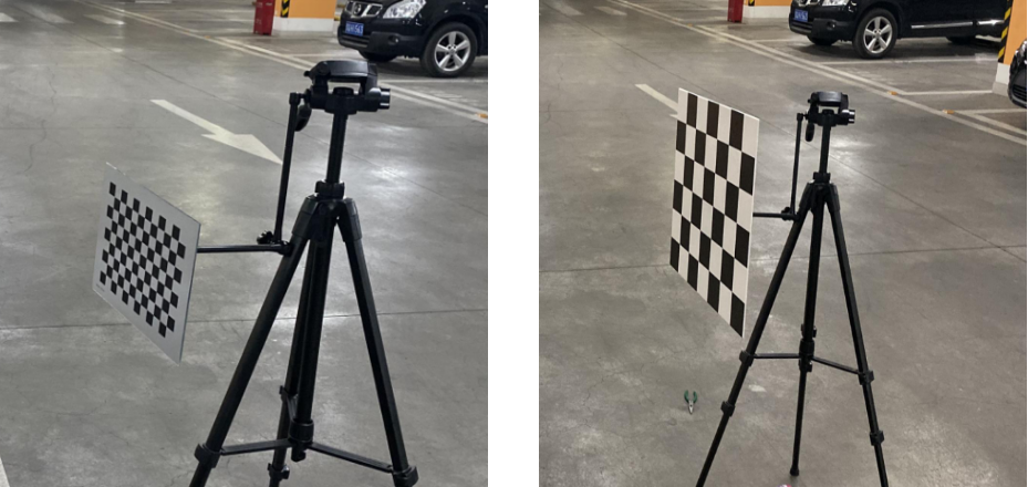
Calibration
The stereo cameras are firstly calibrated with a high-precision checkerboard of small size. This is used to get the stereo rectification parameter and the baseline. Then the camera-LiDAR joint calibration is conducted with another checkerboard to get the rigid transformation. The re-projection error is less than 1pixel.